Tutorial: Create a 3D Terrain in Rhino From Contours
Learn how to create a topographic surface using an AutoCAD Drawing File in 3 easy steps:
1. Source Contour Data
2. Import Contour Data into Rhino
3. Run the Patch Command to create a 3D Surface
Step 1
Source Contour Data
If you have topography data in the form of contours saved as an AutoCAD drawing (.dwg) file and the contour lines already have z-values associated with them, you can proceed to step 2. However, if you do not have recent contour data or your contour data does not have z-values associated, simply click on the button below which will take you to Equator and follow the subsequent steps.
Part 1: Create Site in Equator
- Sign up or log into Equator
- To locate your project, you can either type its name into the search bar or zoom in to its location on the map.
- Select the +NEW SITE button at the bottom left of the screen
- Choose the shape of your site from the left side menu or draw your own boundaries
- Press the Create Site button at the bottom left of your screen

Create a New Site in Equator – choose your shape or draw your site boundaries (the Custom button), name your site, then select Create Site
Part 2: Generate and Download Contours
- Go to the Data menu on the left of your screen, and select the second option Contours as a DWG
- You will see the Generate Contours menu pop up. Select the site you’d like to create contours for, your preferred dataset (the default one will be the highest resolution), and your contour interval (smooth for 1m intervals or detailed for 0.3m intervals). Then select Generate.
- The contours will show up on the map and under the Layers menu. On the Layers menu, select the download arrow.
- You will see the Download menu pop up. Select your preferred format (for this tutorial it will be dwg), the appropriate coordinate system, then select Process.
- Your contours will download into a zipped folder. Make sure to extract the folder before importing the drawing into Rhino.

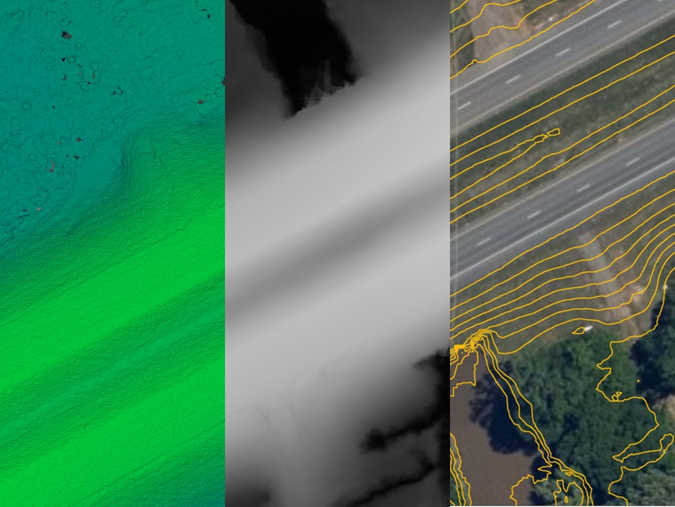
Contour data in Equator for new site
Step 2
Import Contour Data into Rhino
There are two simple ways to import your AutoCAD drawing (.dwg) file into Rhino:
Method 1: Simply drag and drop the .dwg file into Rhino’s interface.
Method 2: File > Import and select your downloaded .dwg file

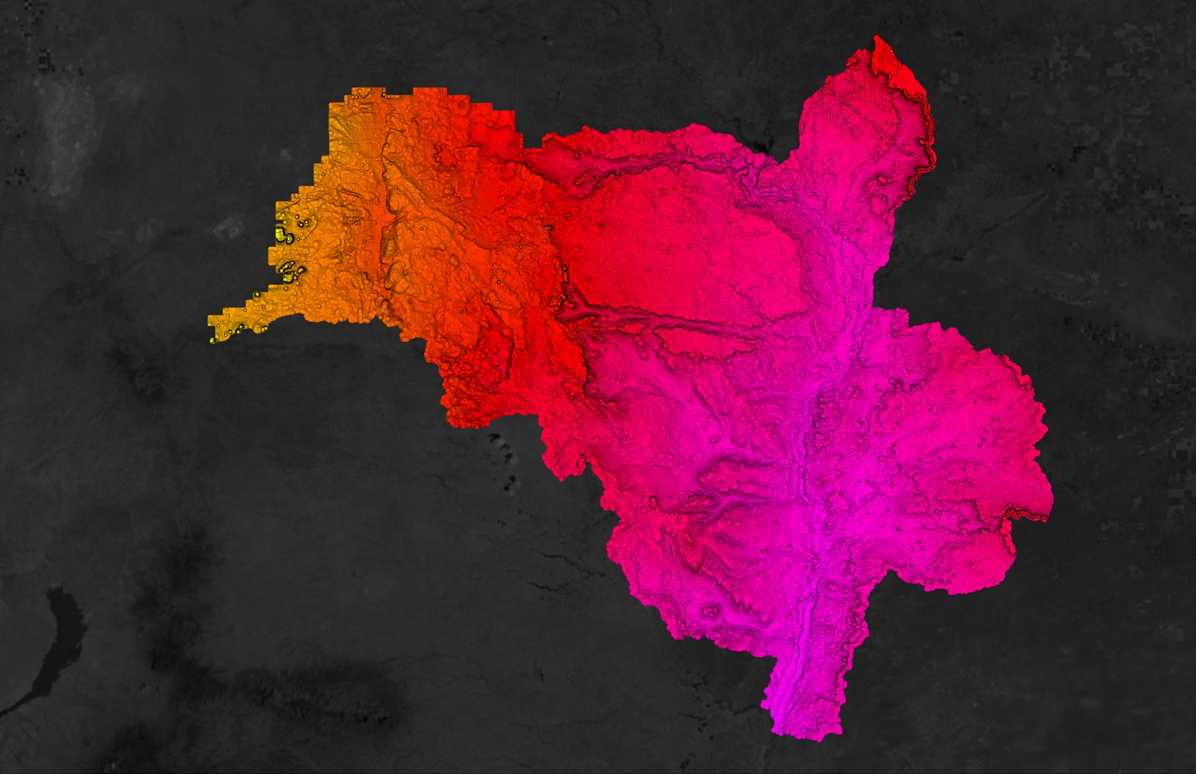
Contour lines downloaded from Equator as an AutoCAD Drawing File (.dwg) brought into Rhino
Step 3
Run the Patch Command to create a 3D Surface
One advantage of using contour data from Equator is that all contour lines come with an assigned z value, which means you don’t have to spend time adjusting lines to the proper elevation.
Select your contour lines and use the command ExtractPt to create points from your contour lines. Then, to create your 3D mesh, simply type “Patch” into the command bar. The Patch command will give you some options:
Sample Point – this is the physical distance along the individual contour lines between sample points.
U – the span count for the automatically generated surface in the u-direction. The default is 10; however, the higher the number, the more accurate your surface (but too high of a number may cause your computer to crash).
V – the span count for the automatically generated surface in the v-direction. The higher the number, the more accurate your surface (however, too high of a number may cause your computer to crash)
Stiffness – this tells us how stiff or bendable the surface is. The bigger the number, the “stiffer” the surface will be and in the case of topography, less accurate.

Patch command will take a little bit of time to complete. Once complete, you will most likely need to trim the excess surface that has been created. Create a square around your contour lines, then use the Trim command.
In the View Menu, you can select how you view the surface (a wireframe, shaded, rendered, etc). Zoom into the surface to make sure you are happy with the accuracy of it. If yes, you’re done! If not, go back and adjust the different options presented in the Patch command.

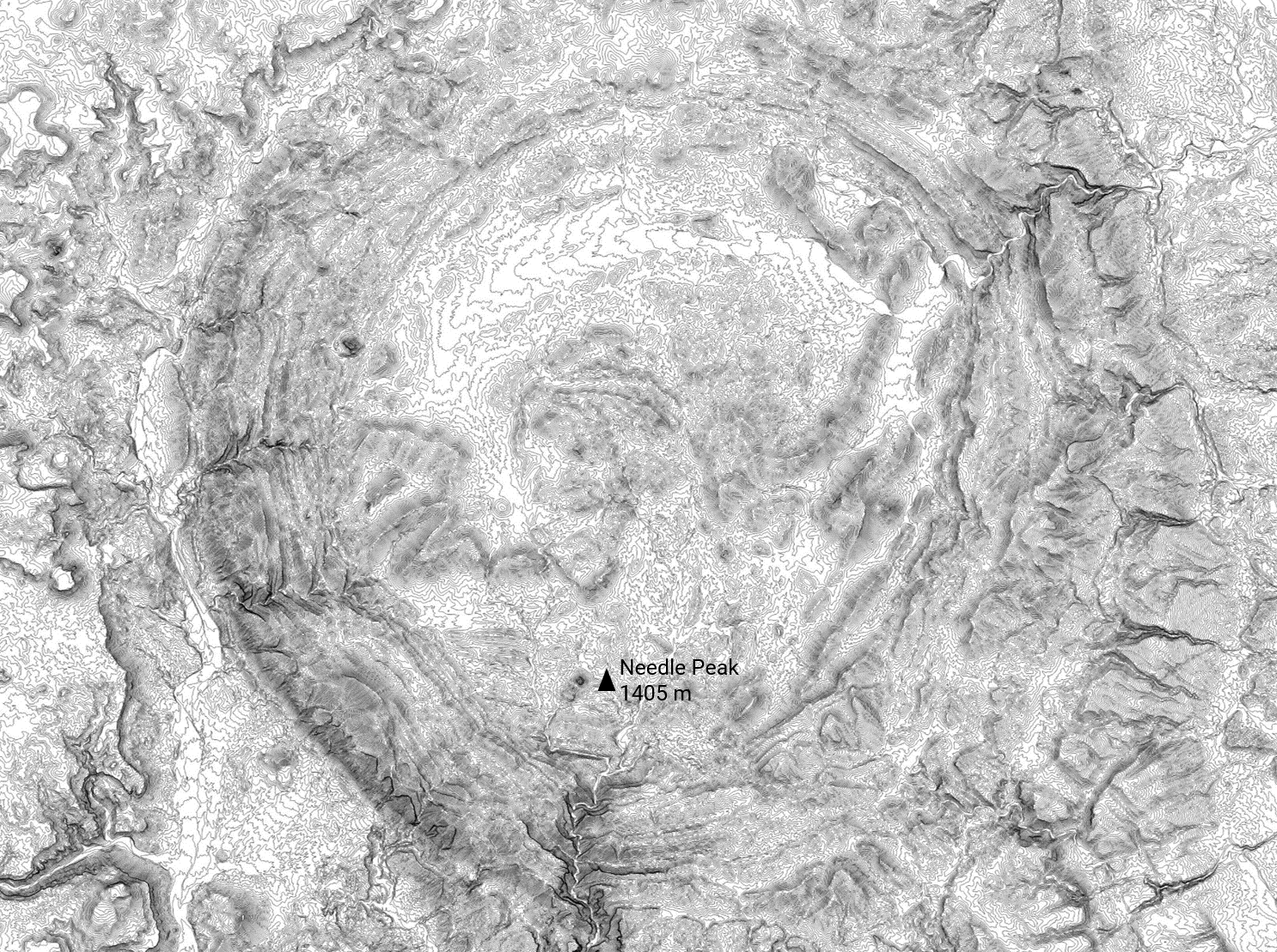
Comparison of contours and the 3D Mesh created from the contours. For this mesh, sample point was set to 0.5, u and v were set to 100, and stiffness was set to 1.

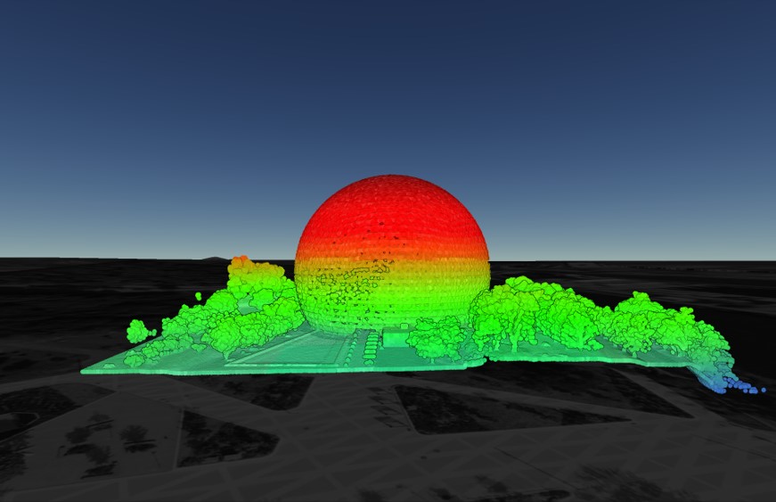
3D Mesh shown as a rendered surface, created from AutoCAD Drawing File (.dwg) contour lines downloaded from Equator