User Guide / What is a Civil 3D surface (TIN versus Grid)?
What is a Civil 3D surface (TIN versus Grid)?
Overview
There are many different ways that a 3D surface can be generated, and advantages and disadvantages to each. In Civil 3D, there are two main kinds of surfaces: TIN and grid.
TIN Surface
TIN stands for triangulated irregular network. This kind of surface is made up of non-overlapping triangles. Each of the triangles represents a face on the surface.
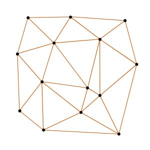
Triangulated irregular network example (source)
A TIN surface can be created from many different types of elevation data, such as points (e.g. a topographic survey), or contours (e.g. polylines). In general, every point, vertex, or node that represents an elevation will be used to create the TIN surface.
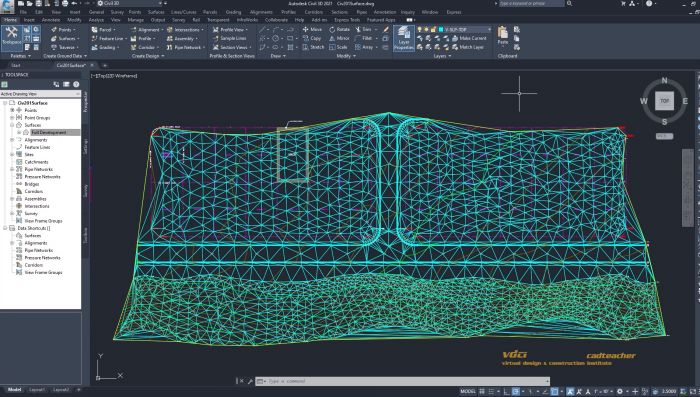
Civil3D TIN Surface (source)
Advantage
- Efficient storage of data
- Variable level of detail based on surface needs
One of the biggest advantages of TIN surfaces is their efficiency in storing data. In a TIN surface, triangles are only created where elevation points exist. In areas where there is limited data, the TIN surface will also have limited triangles. The same is true in the reverse, where there is lots of elevation information, the surface will reflect that detail accordingly.
Imagine, you are surveying a new project site. You need to collect a lot of detail around the road, bridge, and sidewalk to inform your design. In these areas, you collect 1 point every 1m. You also need to collect some data in the surrounding field to understand drainage patterns, but in these areas, you do not require as much detail. Here you collect 1 point every 10 m.
When you turn your surface data into a TIN surface, the resolution of your surface is directly related to the coverage of your survey points. In the field, your TIN surface will be lower resolution with fewer triangles, while on the roadway your surface will be higher resolution with more triangles.
As you can imagine, this approach means that the data storage size is not directly proportional to the physical size of the site.
Disadvantage
- Manual work required to “clean-up” a TIN surface
The main disadvantage of a TIN surface is the level of effort that is required to control the quality of the end product. There is typically a lot of manual work that goes into creating a TIN surface for civil engineering design projects.
Since triangles are generated based on closest elevation nodes only, this can cause problems when the source elevation data includes many different features. For example, if a survey point representing the top of a hydrant is right next to a road point, the TIN surface will connect the two and show a bump in the road.
The job of the civil designer is to ensure that the TIN surface reflects the actual conditions or intended design. This is achieved by creating break lines, adding more points or using other editing techniques. As an example, a break line might be drawn to connect all of the edge of pavement points on a roadway, thus controlling surface behavior, smoothness and continuity.
Grid Surface
A grid surface is made up of elevation points on a regularly spaced grid. Rather than creating more or less 3D faces based on source elevation data (as in the TIN surface), a grid surface will have a pre-defined number of faces based on the desired grid spacing. The storage size required for a grid surface is directly proportional to the size of the site and the specified grid spacing.
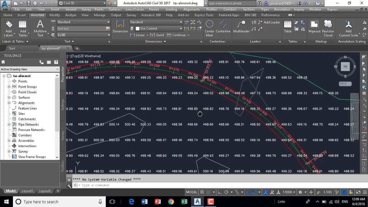
Grid Surface Civil 3D (source)
Advantages
- Smoother, more natural appearance
One of the biggest advantages of grid surfaces is the potential for a smoother more natural appearance of the terrain surface. This is a result of the regular spacing of grid points.
However, this is only true if the source data resolution meets the requirements of the grid surface. This would not apply if the source data was patchy, or sporadic in coverage, such as often the case with a ground-based survey.
Best practices: a grid surface should be created from source elevation data with a resolution that meets or exceeds the needs of the grid surface. For example, a grid surface with 1 m spacing, created from a 0.5 m resolution digital elevation model (DEM) would be acceptable.
Disadvantages
- Inefficient storage of data
- Does not reflect variable complexity in the terrain
The two biggest disadvantages of the grid surface are the static storage size and the inability to use grid sizes to reflect different complexity in the terrain.
If a grid surface was created with a 1 m spacing, it would not be possible to reflect the detail in features that are less than 1 m in size. For example, a 1 m grid surface would not clearly show the elevation differential between the top and the bottom a curb, or any other sudden changes.
Which Civil 3D surface should I choose for my project?
To choose the right surface for your Civil 3D project, there are a few questions you should ask:
- What am I trying to achieve with this project?
- What kind of source elevation data is available?
- Do I need more detail in some areas and less in others?
- How important is data storage size?
- How important is it to have a smooth, natural-looking surface?
- How much time is available to manually improve the surface?
Where can I find elevation data?
Once you have figured out what kind of surface is required for your Civil 3D project, you will likely need to source elevation data. Equator provides access to the highest-resolution elevation data online. We save users days or weeks of ground-based surveys or searching through GIS databases. Using Equator, you will have immediate access to billions of super-accurate elevation points, and the ability to export data for use in Civil 3D.
Equator provides on-demand access to :
- LiDAR point clouds
- Digital elevation models (DEMs in geoTIFF format)
- Digital surface models (DSMs in geoTIFF format)
- Contours (shapefile and dxf format)
Click on the link below to start extracting survey data right now.