Create a Surface and Profiles Along the Surface in Civil 3D
Use Equator to source a Contour Drawing File (.dwg) that can easily be brought into AutoCAD Civil 3D to create a surface. Then use your newly constructed surface to create an alignment and profiles.
Step 1: Source Your Contour Data
Step 2: Create a TIN Surface
Step 3: Choose Your Surface Style
Step 4: Create a Polyline and Alignment
Step 5: Create Profiles and Section Views
Step 1
Source Your Contour Data
If you already have a contour data, skip to the next step.
If you need a contour data, you can source it from Equator with the following steps:
- Sign-in or Create an Account in Equator
- Search for your site location by using the search bar or zooming in
- Create a site boundary using the +NEW SITE button. Select from the default rectangle options or create your own boundary. Don’t forget to name your site!
- Under the Data tab, select Contour from DWG. Choose your parameters and select Generate.
- Your Contour Layer is stored in the Layers tab under your site.
- To download, select the download button (down arrow). Choose your parameters and select ‘Process’.
- The contour file of your site will appear in your Downloads folder (or whichever folder you have directed your downloads to go) in a zipped folder. Unzip the folder before moving onto the next step.
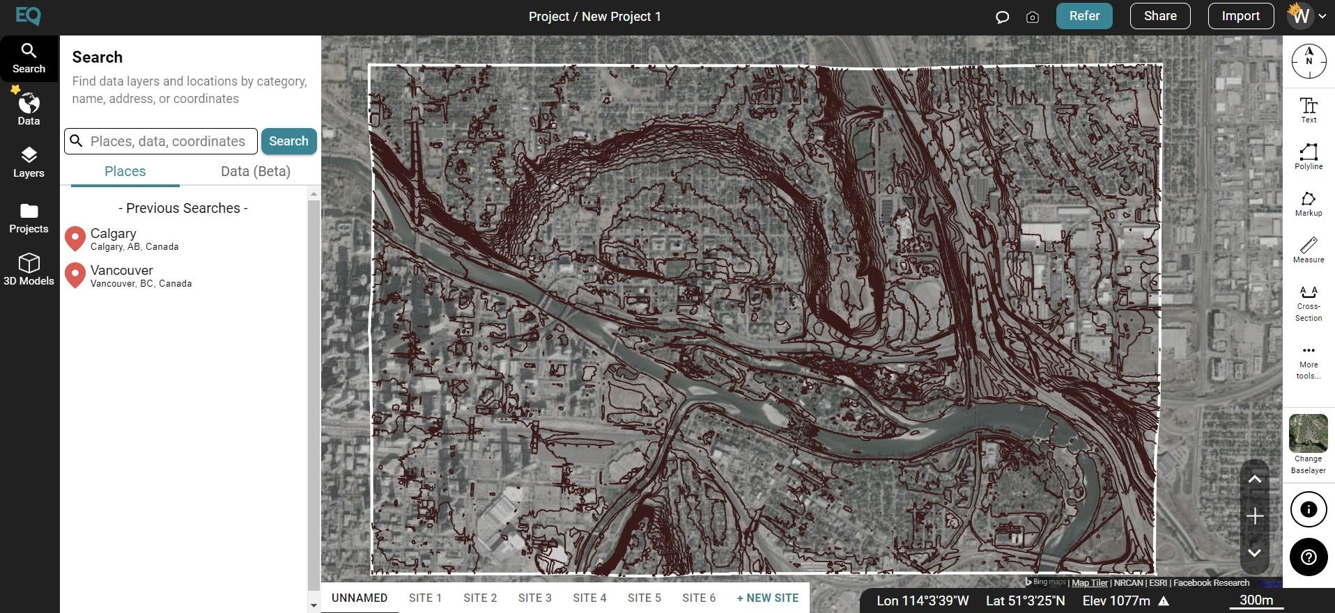
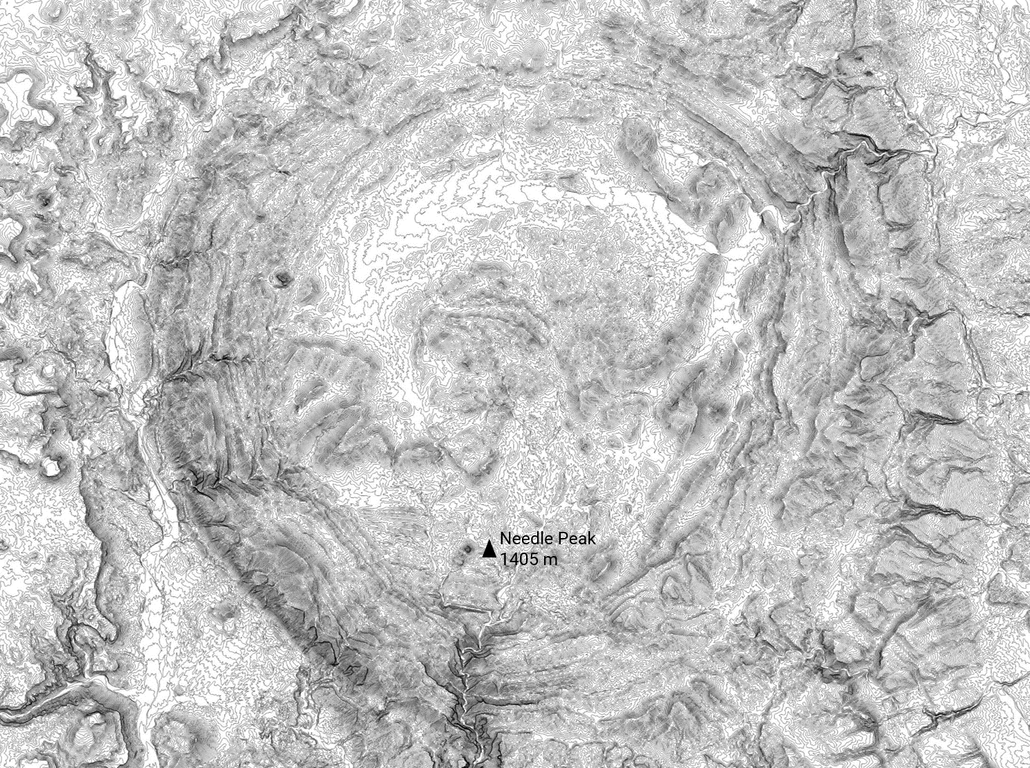
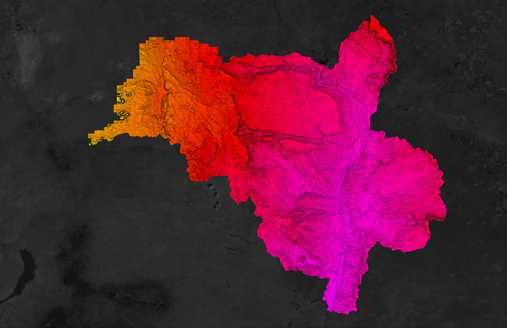
Creating contours to download as a drawing file (.dwg) in Equator
Step 2
Create a TIN Surface in Civil 3D from Contour Lines
By bringing the contour drawing file that you downloaded from Equator into AutoCAD Civil 3D, you can create a topographic surface through the following steps:
- Open Civil 3D
- File > Open > navigate to downloads folder, then select Contour.dwg. Click Open
- Zoom extents by typing Z+enter and E+enter
- Create a copy of the drawing by either creating a new drawing and copy and pasting the contours into the new drawing file, or by going to File > Save As.
- Go to the Prospector Tab and select Surface > Create Surface
- The Create Surface dialog box will appear. Give the surface a name and click Okay
- In the Prospector Tab, click on Surfaces and select the surface you just created. Select Definitions > Contours > Add.
- The Add Contour Data dialog box will appear. Add a description, click okay, then select all the contours.
- Your newly created surface will appear.

Creating a Surface in Civil 3D from Contour.dwg
Step 3
Update Your Surface Style
Update the surface style to show various contour or elevation intervals or to show the triangulation of a TIN surface:
- Turn off the layer that contains the original contour data.
- Select the TIN surface, then select Surface Properties from the Tin Surface ribbon.
- Select Surface Properties from the dropdown menu.
- The Surface Properties dialog box will appear. Change your surface style to your preferred surface type. Click Apply. If you are happy with the style you have selected, click okay.
Step 4
Create a Polyline and Alignment
-
Go to the original contour.dwg file.
- Under the Geolocation ribbon, turn on the aerial basemap by changing Map Off to Map Aerial. This will help you identify the correct alignment of your profile. This is also a good check to make sure your contour.dwg file opened in the correct location.
- Go to the Home ribbon and select polyline (or type the command PLINE)
- Draw the polyline along the alignment which you would like to see a profile
- Turn the aerial image off by going to the Geolocation ribbon, and changing Map Aerial to Map Off.
- Select the polyline, right click and select copy
- Switch to your newly create drawing file with the surface. Make sure you are on Layer 0 (or whichever layer you would like to put your polyline on). Paste the polyline by going to the Home ribbon, Paste, and selecting Paste to Original Coordinates.
- In the Home ribbon, go to Alignment > Create Alignment from Objects. Select the polyline that you just pasted.
- The Create Alignment from Objects dialog box will appear. Give your alignment a name, define the radius, and click okay.

Creating an Alignment in Civil 3D from a Surface
Step 5
Create Profiles and Section Views
-
In the Home ribbon, click on Sample Lines.
- Select the alignment that you just created.
- The Create Sample Line Group dialog box will appear. Click okay.
- In the Sample Lines Tools Menu, select By Range of Sections
- The Create Sample Lines – By Station Range dialog box will appear. Under Station Range, define the start and end. Under Sampling Increments, define your increments. Click okay.
- Define your sections along the alignment by clicking on the start and stop points.
- Under the Home ribbon, select Section Views > Create Multiple Section Views
- Identify the section view origin.
- Click somewhere outside of the tin surface in Model space.
- Your profiles will appear.

Creating Profiles from a Surface Alignment in Civil 3D